ECDIS

ECDIS as an Anti-Grounding Tool

ECDIS can be used as a very effective Anti- Grounding tool when properly set up and used along with appropriate sensors.

The vessels position can be continuously monitored on screen. This facility combined with 

On ENC’s alarms can be generated well before the vessel would run into any danger.

In narrow and congested waters the picture by the ECDIS can effectively influence the action taken onboard by the ..... Difference between a vessel aground (or) afloat.

Positive identification of landmarks / navigational aids /buoys/vessels in conjunction with RADAR Overlay to ascertain the quality of sensor input (Position / Echo Sounder / etc.)

Use of true vector, RADAR Overlay &  Echo Sounder alarms can effectively help navigate safely under / tidal conditions where vessels are experiencing severe set.

  As per IMO performance standards, an ECDIS should have the min.inputs of

  • An Electronic Position Fixing System (EPFS)
  • To a gyrocompass (HEADING)
  • To a speed and distance measuring device (SPEED)

Advantage of  ECDIS over paper Chart:

  Position fixing can be done at required interval without manual interference
  Continuous  monitoring of the ships position
  When interfaced with ARPA/RADAR,target can be monitored continuously
  If two position fixing system are available,the discrepancy in two systems can be identified
  Charts can be corrected with help of CD/online
  Passage planning can be done on ECDIS without referring to other publications 
  Various alarm can be set on ECDIS
  Progress of the passage can be monitored in more disciplined manner ,since other navigational data is available on ECDIS
  Various alarm can be activated to draw the attention of OOW
  More accurate ETA can be calculated
  Anchoring can be planned more precisely

ROTI

INTRODUCTION:

         As per SOLAS 2000 Amendment Chapter V Regulation 19.2.9, it is mandatory for ships over 50,000 GRT to have a rate of turn indicator. IMO recommends that large alteration of courses have to be planned along circular tracks with wheel over point marked.

        The Rate of Turn Indicator (ROTI) is a device that indicates the instantaneous rate at which the ship is turning. It is fitted on ship as an independent fitment integrated with the steering gear/auto pilot.

CONSTANT RADIUS TURN:

In this method radius Radius is kept constant.

CONSTANT RATE TURN:

In this method ROT (/t) is kept constant.

WHEEL OVER POINT (WOP):

It is the point on initial course at which wheel is put over to initiate the turning of the vessel. It is

obtained by intersection of initial course by wheel over line.

The distance between the WOP and the ship commencing its turn is denoted by F and depends on:

 Size of vessel

 Loaded/ballast condition

 Trim

 Type of vessel etc.


BNWAS

PURPOSE OF BNWAS
        The purpose of a bridge navigational watch alarm system is to monitor bridge activity and detect operator disability which could lead to marine accidents.
        The system monitors awareness of the Officer of the Watch (OOW) and automatically alerts the Master or another qualified person if, for any reason, the OOW becomes incapable of performing OOW duties.
This purpose is achieved by series of indications and alarm to alert first the OOW and, if he is not responding, then to alert Master or another qualified person.

OPERATIONAL MODES
The BNWAS should incorporate the following operational modes:
- Automatic (Automatically brought into operation whenever the ship’s heading or track control system is activated and inhibited when this system is not activated)
- Manual ON (In operation constantly)
- Manual OFF (Does not operate under any circumstances)


VDR

 WHAT IS A VDR?

A VDR or voyage data recorder is an instrument installed on a ship to continuously record critical Information related to the operation of a vessel.

It consists of a recording system for a period of at least last 48 hours which is continuously overwritten by the latest data. This recording is recovered and made use of for various purposes, especially for investigation in the events of accidents.

Purpose/benefits of VDR

VDR data can be used for:

1. Accident investigations
2. Response Assessment
3. Training support
4. Promotion of best practices
5. Reduction of insurance cost

MAIN COMPONENTS OF VDR:
1. DATA MANAGEMENT UNIT (OR DATA COLLECTION UNIT)
2. AUDIO MODULE
3. FINAL RECORDING MODULE
4. REMOTE ALARM MODULE
5. REPLAY STATION
6. RESERVE SOURCE OF POWER

The VDR at least must record the following:
Date and time (SVDR)
Ship’s position (SVDR)
Speed and heading (SVDR)
Bridge audio (SVDR)
Communication audio (radio) (SVDR)
Radar data (SVDR)
ECDIS data (SVDR)
Echosounder
Main alarms
Rudder order and response
Hull opening (doors) status
Watertight and fire door status
Speed and acceleration
Hull stresses
Wind speed and direction

What time period can be recorded?
The IMO requires a minimum of 12 hours recording but most manufacturers provide larger storage options often with removable media, which may be used as a management and training tool. 

LRIT

 PURPOSE OF LRIT:

The main purpose of the LRIT ship position reports is to enable a Contracting Government to obtain ship identity and location information in sufficient time to evaluate the security risk posed by a ship off its coast and to respond, if necessary, to reduce any risks. LRIT has also become an essential component of SAR operations and marine environment protection.

CARRIAGE REQUIREMENT

Ships in international voyages - Passenger ships - Cargo ships over 300 t - Mobile platforms

INFORMATION TRANSMITTED

 Identity (Ship’s LRIT Identifier)

 Position (Lat/Long)

 Date and time (UTC)

UPDATE INTERVAL

 Default value 6 hourly

 Update interval remotely selectable

 Minimum interval 15 min

 May be switched off by the Master under certain conditions

THE LRIT SYSTEM CONSISTS OF:

1. The ship borne LRIT information transmitting equipment

2. Communications Service Providers (CSPs)

3. Application Service Providers (ASPs)

4. LRIT Data Centres (DC), including any related Vessel Monitoring System(s) (VMSs)

5. The LRIT Data Distribution Plan (DDP)

6. The International LRIT Data Exchange (IDE), and,

7. LRIT Co-Ordinator

AUTO PILOT

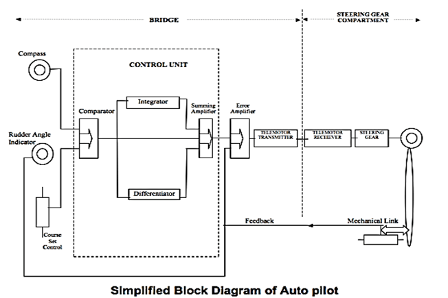
Autopilot is the ship‟s steering controller which automatically manipulates the rudder to decrease the error between the reference heading and actual heading.

Autopilot relieves the helmsman to great extent but definitely autopilot is not a substitute for helmsman.

Autopilot also reduces fuel consumption as the zig-zag course is avoided.

Ship's Auto Pilot Diagram with Sketches | Oways Online

PID Control:
Proportional, Integral and Derivative steering control system, the oscillation is minimized by modifying the error signal produced as the difference between the selected heading and the compass heading.

PROPORTIONAL CONTROL 
The effect on steering when only proportional control is applied causes the rudder to move by an amount proportional to the off-course error from the course to steer and the ship will oscillate on either side of the required course-line.
DERIVATIVE CONTROL
The rudder is shifted by an amount proportional to the rate of change of ship’s deviation from the course. The ship will make good a course which is parallel to the required course and will continue to do so until the autopilot is again caused to operate by external force acting on the ship.
INTEGRAL CONTROL
There are certain errors due to design parameters of the vessel which have to be corrected. Data signals are produced by continuously sensing heading error over a period of time and applying an appropriate degree of permanent helm is used for this purpose. The permanent helm acts as mid-ship.

What are settings of Autopilot  system?
Permanent helm: 
To be used only if a constant influence, like cross wind or beam sea is experienced. If there is a very strong beam wind from starboard side then a permanent 5 degrees starboard helm may be set.
Rudder: 
This setting determines the rudder to be given for each degree of course drifted. Eg. 2 degrees for every 1 degree off course.
Counter rudder:
Determines the amount of counter rudder to be given once v/l has started swinging towards correct course to stop swing. Both rudder & counter rudder to be set after considering condition of v/l (ballast, loaded, etc.). Eg. Laden condition full ahead, not advisable to go over 10 degrees rudder.
Weather:
The effect of weather & sea conditions effectively counteracted by use of this control. This setting increases the dead band width. Comes in handy if vessel is yawing excessively.

What are different Steering modes of Auto Pilot?
Auto/Manual, Follow up, Non Follow up

What is Off course alarm?
It is fitted on the autopilot usually set for 5 or 10 degrees. If difference between actual course & course set by officer for autopilot is more than value set for alarm, it will sound.
This alarm will not sound in case of gyro failure.
Only indication in this case is a gyro failure alarm. Gyro compass & repeaters to compared frequently along with magnetic compass.

What are disadvantages of Autopilot?
The auto pilot gives rudder according to the gyro heading.
If the gyro fails the autopilot will still keep the gyro course & wander with the gyro.
Gyro alarm to be taken seriously or the v/l will collide if there are sudden alterations.

Settings which depend upon ships loading conditions:
Rudder  Setting             
Determines  the rudder to be given for each degree course drift. e.g. 2° degrees rudder for every 1°off course.
Counter rudder
Determines the amount of counter rudder to be given to stop swing as the ship approaches the correct course,
Maximum Rudder
Determines  the maximum rudder angel that can be set. For example, In full load is advisable not to give more than 10° rudder.
Permanent Helm 
Use only when a ship tends to veer off towards one side of the course due to strong cross wind or a beam sea.
Weather
The effect of weather & sea conditions which causes ship to yaw excessively, can be counteracted by use of this control.
Off Course Alarm
Higher setting in open sea and smaller setting in restricted waters.
Caution:  This alarm will not sound in case of gyro failure. Only indication in this case is a gyro failure alarm.
Solution: Frequent comparison of Gyro and Magnetic Compass.


What is AUTO ADAPTIVE STEERING SYSTEM
This is an advanced version of the PID control which adapts to the steering capabilities of the ship as well as the wind and weather conditions.

The ship’s hull dynamic characteristics keep changing with the change in the load condition, speed, depth of water, wind and weather conditions etc. In the PID autopilot, the controls have to be re-adjusted to get the optimum steering but in the adaptive autopilot, the estimation algorithm is incorporated so that the optimum steering is obtained without re-adjusting the controls.
Processing Unit in the ADAPTIVE mode and the control algorithm is divided into three units as follows:-
• Estimation Unit
• Optimal Control Unit and
• Adaptive Kalman Filter

The ship should not be on autopilot mode under the following situations:
 In narrow channels
 At slow speeds
 In areas of heavy traffic
 In rough weather conditions
 When vessel is under pilotage
 In poor visibility

The autopilot should not be used for following:
 For large alteration of course (unless the autopilot is designed for the purpose)
 Never for collision avoidance

AIS

SOLAS CARRIAGE REQUIREMENT

The carriage of AIS on board ships is governed by SOLAS regulation V/19.2.4. The regulation requires AIS to be fitted aboard all ships of

  • 300 gross tonnage and upwards engaged on international voyages,
  •  cargo ships of 500 gross tonnage and upwards not engaged on international voyages and
  • All passenger ships irrespective of size.
PURPOSE:
        The purpose of AIS is to help identify ships, assist in target tracking, assist in search and rescue operation, simplify information exchange (e.g. reduce verbal mandatory ship reporting) and provide additional information to assist situation awareness. In eneral, data received via AIS will improve the quality of the information available to the OOW, whether at a shore surveillance station or on board a ship.

WHAT IS AIS?
        Very simply, the Automatic Identification System is a broadcast transponder system, operating in the VHF maritime mobile band.
AIS operates principally on two dedicated VHF frequencies or channels:
AIS 1 - 161.975 MHz - channel 87B (Simplex, for ship to ship) and
AIS 2 - 162.025 MHz - channel 88B (Duplex for ship to shore).

        AIS uses Self-Organizing Time Division Multiple Access (SOTDMA) technology to meet this high broadcast rate of 9600 bits per second and ensure reliable ship-to-ship operation.It normally works in an autonomous and continuous mode, regardless of whether it is operating in the open seas, coastal or inland areas.
        Each station determines its own transmission schedule (slot), based upon data link traffic history and knowledge of future actions by other stations.
A position report from one AIS station fits into one of 2250 time slots established every 60 seconds.
DATA TRANSMITTED
    AIS transmit the following categories of information:
  • Static information
  • Dynamic information
  • Voyage related information
Short safety-related messages
Static information: (Every 6 min and on request)
 MMSI
 IMO number (where available)
 Call sign & name
 Length and beam
 Type of ship and
 Location of the position-fixing antenna
Dynamic information: (Dependent on speed and on speed/course alteration)
 Ship’s position with accuracy indication and integrity status
 Position time stamp (in UTC)
 Course over ground (COG)
 Speed over ground (SOG)
 Heading
 Navigational status (e.g. at anchor, underway, aground etc. And
 Rate of turn (where available).
Voyage related information (Every 6 min, when is data amended, or on request)
 Ship’s draught
 Hazardous cargo (type)
 Destination and ETA and
 Route plan (waypoints)
Short safety-related messages: Free format text message (sent as needed) addressed to one or more specified destinations or to all stations in the area. The content should be relevant to safety messages e.g. buoy missing, ice-berg sighted etc.

REPORTING INTERVAL

At Anchor / Moored--3 minutes
At Anchor / moored and moving faster than 3 konts--10 seconds
Speed 0 – 14 Konts--10 seconds
And changing course--3 1/3 seconds
Speed 14 - 23 Knots--6 seconds
And changing course--2 seconds
Speed > 23 Knots--2 seconds
And changing course--2 seconds

AIS TYPES
Class A mandated by the IMO for vessels of 300 gross tonnage and upwards engaged on international voyages, cargo ships of 500 gross tonnage and upwards not engaged on international voyages and passenger ships irrespective of size.
Class B provides limited functionality and is intended for non-SOLAS vessels. It is not mandated by the International Maritime Organization (IMO) and has been developed for vessels such as work craft and pleasure craft


RADAR

 The term “Radar” is an acronym for Radio Detection and Ranging”.

Principle:

A radio wave is transmitted and received back by the scanner. The time is calculated between transmission and receiving back this wave. The speed of the radio wave is known and thus the receiver unit calculates the distance of the target. After processing, it displays this information on the display screen. The rotating scanner also calculates the bearing of the target and displays on the radar screen.

  IMPORTANT CHARACTERISTICS OF A RADAR .

1) VERTICAL BEAMWIDTH (VBW):

IT IS THE VERTICAL ANGLE AT THE SCANNER CONTAINED BETWEEN THE UPPER &THE LOWER EDGES  OF THE RADAR SETS BEAM.AS PER THE IMO STANDARDS THE RADAR SET SHOULD FUNCTION IF THE VESSEL IS ROLLING OR PITCHING +_10 DEG WITHOUT DETERIOATION.

MARINE SETS HAVE A VBW OF 15-30 DEG.

2) HORIZONTAL BEAM WIDTH (HBW):

IT IS THE HORIZONTAL ANGLE AT THE SCANNER CONTAINED  BETWEEN THE LEADING & THE TRAILING EDGE OF THE RADAR BEAM .IT CAUSES ALL THE TARGETS TO APPEAR LARGER IN AZIMUTH  BY AN AMOUNT  EQUAL TO HLF THE HBW.

3) PULSE LENGTH:

DUE TO THE PULSE LENGTH THE POINT OF THE PPI APPEARS TO HAVE A RADIAL DEPTH OF HALF PL IN METERS.IT IS THE TIME INTERVAL BETWEEN THE TIME TAKEN BY THE PULSE TO LEAVE 5HE LEADING AND THE TRAILING EGDES.

4) PULSE REPITION FREQUENCY/(PRF):

IT IS THE NUMBER OF PULSES SET OUT THROUGH THE SCANNER IN ONE SECOND. IT ISBETWEEN 500-4000.LONGER RANGES HAVE LOW PRF.SHORTER RANGES NEED HIGH PRF FOR BETTER PICTURE  RESOLUTION.

5) WAVELENGTH:

AFTER RADAR ENERGY  LEFT  THE SCANNER THE PATH ENERGY &TRABEL ARE INFLUENCED  BY :1)ATTENUATION,      2)DIFFRACTION.

X BAND:  3CM WAVELENGTH.(9300-9500 MEGS)

S BAND :10 CMS WAVELENGTH.(2900-3100 MEGS)

3CM :GREATER ATTENUATION ,LESS DIFFERENCE ,GOOD FOR SHORT RANGES.

10 CM: LESS ATTENUATION, MORE DIFFERENCE,GOOD FOR LONGER RANGES.


LIMITATIONS OF RADAR SET:

1)RANGE DISCRIMINATION:

IT OIS THE ABILITY OF THE RADAR SET TO CLARLY DISTINGUISH TWO SMALL TARGETS ON THE SAME BEARING AT SLIGHTLY DIFFERENT RANGES.

THE DISTANCE BETWEEN THE TWO TARGETS IS EQUAL TO OR LESS THAN 1/.2 PL.

2)BEARING DISCRIMINATION :IT IS THE ABILITY OF THE RAAR SET TO CLEARLY EXTINGUISH TWO TARGETS OF THE SAME RANGE AND SLIGHTLY DIFFERENT BEARINGS.FACTOR:HBW.

3)MINIMUM RANGE:

A) THE PULSE LENGTH :THE TR CIRCUIT PREVENTS THE TX OF ANY SIGNAL BEFORE RECEIVING IT.HENCE,THE THEOROTICAL MINIMUM RANGE OF DETECTION IS REPEATED BY HALF PL IN MINUTES. 

A PL OF 0.2 MICRO  WOULD HAVE ARANGE OF 30 MTRS.

B) DEIONISATION DELAY:  A SMALL DELAY OCCURS IN THE TR CELL BETWEEN THE COMPLETION OF TX &RECEIVING. A DELAY OF 0.5 MICROSECS.WOULD INCREASE  THE MINIMUM RANGE A FURTHER BY 7.5 MTRS. 

C)THE VBW +THE HEIGJHT  OF THE SCANNER.

4)MAXIMUM RANGE:

A)HEIGTH OF THE SCANNER INCREASES  THE SCANNER , THE INCREASE OF RANGE.

 B) POWER OF THE SET ,MARINE RADAR SET TRANSMITS AROUUND 25 TO 60 KWTS.

C) WAVELENGTH     : 10 CMS HAVE EXTENDED RANGE AS COMPARED TO 3 CMS.

D) PULSE REPETION FREQUENCY:

E) PULSE LENGTH: LONG PULSES ENSURES BETTER MAXIMUM RANGES THAN SHORTER PULSES  CAUSE ,LONG PULSES  HAVE MORE WAVELENGTH IN THEM.

F) VBW/HBW:THE NARROWER THE BEAM WIDTH THE GREATER THE DIRECTIONAL CONCENTRATION,INCREASES THE RANGE.

5)ANOMALOUS PROPOGATION:  SUPER REFRACTION CAUSES AN INCREASE IN MAXIMUM DETECTION RANGE. THIS IS CAUSED DUE TO  METEOROLOGICAL FACTORS LIKE TEMPERATURE INVERSION.

RANGE ACCURACY: ACCORDING TO IMO PERFORMANCE STANDARDS THE ERROR IN THE RANGE OF AN OBJECT SHOULD NOT BE MORE THAN 1.5% OF THE MAXIMUM RANGE SCALE IN USE OR 70 MTS WHICHEVER IS THE GREATER.

BEARING ACCURACY: ACCORDING TO THE IMO PERFORMANCE STANDARDS THE OBJECT SHOULD BE MEASURED WITH +_ 1 DEGREE OF ACCURACY.

THE FOLLOWING ARE THE MERITS/DEMERITS OF USING HEADS UP MODE / NORTH UP MODE:

HEADS UP DISPLAY:
1) PICTURE SMUDGES IN AZIMUTH DURING ALTERATION OF COURSE.
2) BECAUSE OF SMUDGING ACCURATE BEARINGS CANNOT BE TAKEN AT THAT TIME.
3) PLOTTING TENDS TO BE HIGHLY INACCURATE DURING SEVERE YAWS.
4) ALL BEARINGS ARE RELATIVE.
5) RADAR PICTURE IS HEAD UP WHILE CHART IS NORTH UP.
6) AFTER LARGE ALTERATIONS OF COURSE THE OBSERVER TENDS TO GET DIS- ORIENTED WITH PLOTTING AS ALL TARGETS HAVE SHIFTED.
7) NO INDICATION ON THE SCREEN OF GYRO COURSE STEERED.TEMPORARY WANDERINGS MAY GO UNDETECTED.
NORTH UP DISPLAY:
1) PICTURE DOESN’T SMUDGE IN AZIMUTH AND BEARINGS CAN BE TAKEN ACCURATELY.
2) PLOTTING IS QUITE ACCURATE EVEN DURING HEAVY YAWS.
3) ALL BEARINGS ARE TRUE.
4) CHART AND PPI. BEING NORTH UP IT IS EASIER TO RELATE.
5) THERE IS NO DISORIENTATION DUE TO ATERATION OF COURSE.
6) HEADING MARKER INDICATES THE GYRO COURSE STEERED AT ALL TIMES.

Advantages of RADAR:

1. Used at night and during periods of reduced visibility when visual means of navigation are limited or impossible.
2. Available at greater ranges from land. 
3. Fixes may be obtained from a single object.
4. Fixes obtained quickly & accurately.
5. Can locate & track shipping and storms

Disadvantages of RADAR:
1. Subject to mechanical & electrical failure.
2. Both min & max range limitations. 
3. Interpretation of display is not always easy.
4. Bearing LOP’s are inaccurate.
5. Small objects may not be detected in highseas.

Radar Performance test

Radar Performance test checks the transmission and receiving power of the radar. For example if the transmission power of the radar is not enough, radar may not be able to paint some of the target at all. Or radar may only be able to paint the targets with very less sensitivity (faint echoes).

What are controls of RADAR?
1. Brilliance
2. Focus
3. Gain
4. Tuning
5. Anti sea clutter
6. Anti rain clutter
7. Heading marker

What are APPA alarms/list of ARPA alarms?
1. Guard zone alarm.
2. Danger target alarm.
3. Lost target alarm.
4. ARPA malfunction

.


EM Log

 Principles of Electromagnetic Speed Log:-

  • The electromagnetic log is based is upon the induction law, which states that if a conductor moves across a magnetic field, an electro motive force (e.m.f.) is set up in the conductor.
  • Alternatively, the e.m.f. will also be induced if the conductor remains stationary and the magnetic field is moved with respect to it.
  • The induced e.m.f. is directly proportional to the velocity.
  • Velocity when integrated with time gives distance
  • The induced e.m.f. "E" is given by the following:

E = F X L X V

  • Where F = magnetic field
  • L = the length of the conductor
  • V = the velocity of the conductor through the magnetic field.

Errors / Limitations:
Siting of the probe is critical. This is so since if too close to the hull then due to the non-linearity of the hull form the speed of the water flow may give a wrong representation of the vessels speed. This is minimized by careful siting of the sensor as well as by calibrating the instrument while installation.
Pitching and Rolling also give rise to errors however these are reduced by having an electrical time constant that is longer than a period of vessel motion. A welladjusted log can have an accuracy of better than 0.1 percent of the speed range.
Sign of Speed, it can show astern speed as well, but without sign if AC current is used, if DC current is used to create the magnetic field it will show sign of speed range. This type of log can give only speed through water and is greatly affected by the current flowing under the ship.
While navigating in area with greater current, one must exercise precautions.

Advantages
  • No moving parts
  • Less affected by sea growth than Pit sword
Disadvantages
  • Salinity and temperature of water affect calibration.
  • Measurements affected by boundary layer, (water speed slowed down close to the hull by friction).
  • Provides boat/ship speed relative to water not ground. Current affects accuracy.

Doppler log

 Principle:

Whenever there is a relative movement between a transmitting source and a receiver, there will be a ‘Doppler shift’ in the frequency received. This shift is termed as Doppler effect.

            fr= ft (c+v)/(c-v)

Where

fr = Received Frequency

ft = Transmitted frequency

c =Velocity of sound in Sea Water (1500m/sec)

v = Velocity of the vessel

How Doppler log works?
A transducer emits continuous a high frequency sound pulse in the forward direction at an angle of 60° to the keel.
Higher the sound frequency, smaller the transducer, narrower the beam and higher the accuracy.
The beam bounces back from the sea bottom.
The frequency of the bottom echo will be higher when the ship is moving ahead or lower if she is moving astern.
The Doppler equation is solved to obtain ship’s speed.
When signal is bounced off the sea bed, (called Bottom Track), the speed displayed the “Speed over the ground (SOG)”    

Advantages of Doppler Log:
Most accurate
Can measure ahead, astern & athwartship movements
Can be used for ocean navigation as well as berthing and maneuvering in close waters.
Can measure very low speeds
This log is most prevalent in today’s marine world.

What is Janus Configuration?
Most Doppler logs have Janus Configuration where
Transducers pointing ahead measures speed.
Transducer pointing Astern is used for accuracy check.
Transducers point abeam to measure athwart ship speed (while berthing).

Errors of Doppler log:
Error in transducer orientation:- The transducers should make a perfect angle of 60° with respect to the keel or else the speed indicated will be inaccurate.
Error in oscillator frequency:- The frequency generated by the oscillator must be accurate and constant. Any deviation in the frequency will result in the speed showing in error.
Error in propagation:- The velocity of the acoustic wave at a temperature of 16°C and salinity of 3.2% is 1505 m/sec but taken as 1500 m/sec for calculation. This velocity changes with temperature, salinity and pressure. To compensate the error due to temperature change, a thermister is mounted near the transducer and change in velocity of the acoustic wave through the water from the standard value due to the change in sea water temperature is accounted for.
Error in ships‟ motion:- During the period of transmission and reception, the ship may have a marginal roll or pitch and thereby the angle of transmission and reception can change and a two degree difference in the angle of transmission and reception can have a 0.10% error in the indicated speed, which is marginal and can be neglected.
Error due to rolling/pitching:- The effect of pitching will cause an error in the forward speed and not the athwartship speed. Similarly, rolling will have an effect on the athwartship speed, not the forward speed.
Actual speed = Indicated speed/Cosß
Error due to inaccuracy in measurement of frequency:- The difference in the frequencies received by the forward and aft transducers must be measured accurately. Any error in this will be directly reflected in the speed of the vessel.
Error due to side lobe:- When the side lobe reception dominates over the main beam reception, there will be an error in the speed indicated. The error is more pronounced on a sloping bottom as the side lobe is reflected at a more favourable angle and will have path length less than the main beam. This error can be eliminated with the help of the Janus configuration and to reduce this error, the
beam of the transmitted acoustic wave is reduced.

Echo sounder

 Basic Principle


Short pulses of sound vibrations are transmitted from the bottom of the ship to the seabed. These sound waves are reflected back by the seabed and the time taken from transmission to reception of the reflected sound waves is measured.  Since the speed of sound in water is 1500 m/sec, the depth of the sea bed is calculated which will be half the distance travelled by the sound waves.

The received echoes are converted into electrictal signal by the receiving transducer and after passing through the different stages of the receiver, the current is supplied to stylus which burns out the coating of the thin layer of aluminium powder and produces the black mark on the paper indicating the depth of seabed. 
COMPONENTS
Basically an echo sounder has following components:
Transducer – to generate the sound vibrations and also receive the reflected sound vibration.
Pulse generator – to produce electrical oscillations for the transmitting transducer.
Amplifier – to amplify the weak electrical oscillations that has been generated by the receiving transducer on reception of the reflected sound vibration. 
Recorder  - for measuring and indicating depth. 
CONTROLS
An echo sounder will normally have the following controls:
Range Switch – to select the range between which the depth is be checked e.g.  0- 50 m, 1 – 100 m, 100 – 200 m  etc.  Always check the lowest range first before shifting to a higher range.
Unit selector switch – to select the unit feet, fathoms or meter as required.
Gain switch – to be adjusted such that the clearest echo line is recorded on the paper.
Paper speed control – to select the speed of the paper – usually two speeds available.
Zero Adjustment or Draught setting control – the echo sounder will normally display the depth below the keel.  This switch can be used to feed the ship’s draught such that the echo sounder will display the total sea depth.  This switch is also used to adjust the start of the transmission of the sound pulse to be in line with the zero of the scale in use.
Fix or event marker  - this button is used to draw a line on the paper as a mark to indicate certain time e.g. passing a navigational mark, when a position is plotted on the chart etc.
Transducer changeover switch – in case vessel has more than one switch e.g. forward and aft transducer.
Dimmer – to illuminate the display as required.  
Pulse Length
The pulse length is the duration between the leading edge and the trailing edge.The pulse length determine the minimum distance that can be measured by the echo sounder.The minimum measurable distance will be equal to the half of the pulse length.for the shallow water short pulse is used while for the deeper water long pulse is used.
Pulse repetition frequency
This is the nos of pulse transmitted per second.This determines the maximum range that can be measured by the echo sounder.The PRF is normally automatically selected and changes as the range scale is changed.for lower range,High PRF is used whereas for the higher range ,low PRF is used.

RANGING
In echo sounder the stylus is moving with certain constant speed and transmission takes place when the stylus passes the zero marks.When the higher range is selected the speed of the stylus is reduced as stylus has to paper for the longer duration.This system is called the ranging.
PHASING
In phasing the speed of the stylus motor remains constant.In stead of changing the speed of the stylus,the transmission point is advanced.
The sensors are positioned around the stylus belt.The magnet generates the pulse when it passes the sensors which in turns activate the transmitter.


ERRORS OF ECHO SOUNDER
1.Velocity of propagation in water:
      The velocity taken for the calculation of the is 15oom/sec.The velocity of the sound wave is changing due to the change of the salinity and temperature of the sea water. As velocity is varying hence depth recorded will be erroneous.
2. STYLUS SPEED ERROR:The speed of the stylus is such that the time taken by the stylus to travel from top to bottom on chart is same as the time taken by sound wave to travel twice the range selected. but due to fluctuation in voltage supplied to stylus motor ,will cause error in the recorded depth.
3. PYTHAGORAS ERROR:
    This error is found when two transducer are used one for transmission and one for reception.This error is calculated using the Pythagoras principle.
4.Multiple ECHO:The echo may be reflected  no of times from the bottom of the sea bed,hence providing the multiple depth marks on paper.
5.The thermal and density layers:
     The density of the water varies with temperature and salinity ,which all tends to form different layers.The sound wave may be reflected from these layers .
  6.Zero line adjustment error:
    If the zero is not adjusted properly,it will give error in reading
7.CROSS NOISE:
    If sensitivity of the amplifier is high,just after zero marking a narrow line alongwith the several irregular dots and dashes appear and this is called cross noise.The main reasons for the cross noise are aeration and picking up the transmitted pulse.If intensity of cross noise is high,it will completely mask the shallow water depths.This is controlled by swept gain control circuit.
 8.AERATION:
  When the sound wave is reflected from the reflected from the air bubbles,it will appear as dots,this is known as aeration.

Popular topics